
Chapters
- Contents1
- Description and Specifications3
- Chapter 1 - Engine8
- Data8
- Accessory removal9
- Engine disassembly10
- Crankshaft and flywheel14
- Cylinder block16
- Pistons and connecting rods21
- Camshaft and valve mechanism26
- Cylinder head and front cover30
- Oil pump30
- Water pump32
- Governor34
- Oil pan, intake and exhaust manifolds38
- Assembly of engine40
- Installation of accessories46
- Definition of fits48
- Fits and tolerances50
- Torque wrench readings51
- Carburetor52
- Servicing the starter58
- Chapter 2 - Transmission61
- Chapter 3 - Power Take-Off71
- Chapter 4 - Belt Pulley75
- Chapter 5 - Rear Axle79
- Chapter 6 - Hydraulic System89
- Chapter 7 - Steering Gear101
- Chapter 8 - Service Bulletins111
- Bulletin Attachments126
Chapter 1 - Engine
Assembly of engine page 43
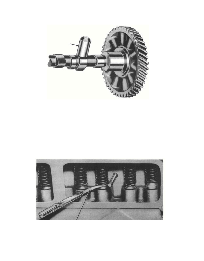 Fig. 50—Push Rod on Heel of Camclearance exceeds 0.012 inch intake and 0.016 inch exhaust, select alonger valve, or reface the valve or valve seat to decrease the clear-ance. If the clearance is less than 0.010 inch intake or 0.014 inchexhaust, select a shorter valve or remove the valve assembly, andgrind the lower end of the valve stem until 0.010 to 0.012 inch(intake) and 0.014 to 0.016 inch (exhaust) is established.f. Install Connecting Rod and Piston Assemblies. Select thepiston assemblies for each cylinder as outlined in section 123. Oil43Fig. 51—Checking Clearance Between Valve Stem and Push Rod3695-47§131.f.PUSH RODRM-519Thickness GaugeRM-520
Free to read online. Contents · Where is the serial number on a 9N, 2N or 8N?