
Chapters
- Contents1
- Description and Specifications3
- Chapter 1 - Engine8
- Data8
- Accessory removal9
- Engine disassembly10
- Crankshaft and flywheel14
- Cylinder block16
- Pistons and connecting rods21
- Camshaft and valve mechanism26
- Cylinder head and front cover30
- Oil pump30
- Water pump32
- Governor34
- Oil pan, intake and exhaust manifolds38
- Assembly of engine40
- Installation of accessories46
- Definition of fits48
- Fits and tolerances50
- Torque wrench readings51
- Carburetor52
- Servicing the starter58
- Chapter 2 - Transmission61
- Chapter 3 - Power Take-Off71
- Chapter 4 - Belt Pulley75
- Chapter 5 - Rear Axle79
- Chapter 6 - Hydraulic System89
- Chapter 7 - Steering Gear101
- Chapter 8 - Service Bulletins111
- Bulletin Attachments126
Chapter 1 - Engine
Camshaft and valve mechanism page 26
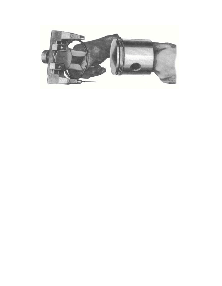 Fig.24—InstallingPiston RingonPistond. Assemble Piston, Piston Pin, and Connecting Rod.Install the piston which was previously fitted (par. a (1) (a) above)for the particular cylinder to the connecting rod previously selectedand having the number of that cylinder. Hold the piston in placeon the connecting rod. Install a piston pin in the piston and con-necting rod, and install a piston pin retainer in each piston pinbore groove.e. Fitting and Installing Piston Rings. Place a new pistonring in the cylinder, and press it about half-way down into the cyl-inder bore with the bottom of a piston so the ring will be square withthe cylinder wall. Measure the ring end gap with a thickness gauge(fig. 23). If the gap is less than 0.012 inch, remove the ring. Place thering in a jig, and file it with a fine cut file until the correct gap (0.012to 0.017 inch) is established. If the gap exceeds 0.035 inch, an oversizering must be used. Roll the new piston ring around its groove in thepiston. The top ring should roll freely and not have a clearance of lessthan 0.0015 inch or more than 0.0035 inch. The lower rings shouldroll freely and not have a clearance of less than 0.001 inch or morethan 0.004 inch. Install the piston ring on the pistons with a pistonring expander (fig. 24). Repeat the entire above procedure for eachpiston ring124. CAMSHAFT AND VALVE MECHANISM.The disassembled camshaft and valve assemblies are shown infigs. 25 and 26.a. Camshaft. Thoroughly clean the camshaft and camshaftgear. Replace a camshaft that has excessively scored or damaged§ 124. a.3695-4726Piston Ring Remover and ReplacerRM-638
Free to read online. Contents · Where is the serial number on a 9N, 2N or 8N?