
Chapters
- Contents1
- Description and Specifications3
- Chapter 1 - Engine8
- Data8
- Accessory removal9
- Engine disassembly10
- Crankshaft and flywheel14
- Cylinder block16
- Pistons and connecting rods21
- Camshaft and valve mechanism26
- Cylinder head and front cover30
- Oil pump30
- Water pump32
- Governor34
- Oil pan, intake and exhaust manifolds38
- Assembly of engine40
- Installation of accessories46
- Definition of fits48
- Fits and tolerances50
- Torque wrench readings51
- Carburetor52
- Servicing the starter58
- Chapter 2 - Transmission61
- Chapter 3 - Power Take-Off71
- Chapter 4 - Belt Pulley75
- Chapter 5 - Rear Axle79
- Chapter 6 - Hydraulic System89
- Chapter 7 - Steering Gear101
- Chapter 8 - Service Bulletins111
- Bulletin Attachments126
Chapter 1 - Engine
Carburetor page 52
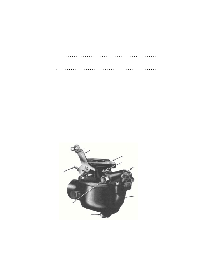 4-CYLINDER ENGINE CARBURETORSectionDisassembly221Cleaning, Inspection, and Repair222Assembly223221. DISASSEMBLY.This procedure consists of removing all parts from the carburetor,such as the choke, throttle valve, levers, jets, etc.a. Remove Throttle Body From Carburetor Body. Remove themain adjustment ratchet screws, and remove the ratchet (fig. 18).Remove the main adjustment needle assembly from the throttle body.Remove the four screws which secure the throttle body to the carbure-tor body. Separate the two units.b. Disassemble Throttle Body. Remove the float lever shaft,float, and float needle valve (fig. 18) from the throttle body. Removethe gasket and venturi. Remove the idler jet and economizer jet witha jet wrench or a small screw driver. Remove the idle adjustingneedle. Remove the float needle seat (fig. 18) with a jet wrench.Figure 17—4-Cylinder Engine Carburetor3675-48-C§221.b.52THROTTLE LEVER AND SHAFTTHROTTLE BODYIDLE ADJUSTMENTMAIN ADJUSTMENTCARBURETORBODYIDLE SPEEDADJUSTMENTFUEL INLETSTRAINERDRAIN PLUGRM-453
Free to read online. Contents · Where is the serial number on a 9N, 2N or 8N?