
Chapters
- Contents1
- Description and Specifications3
- Chapter 1 - Engine8
- Data8
- Accessory removal9
- Engine disassembly10
- Crankshaft and flywheel14
- Cylinder block16
- Pistons and connecting rods21
- Camshaft and valve mechanism26
- Cylinder head and front cover30
- Oil pump30
- Water pump32
- Governor34
- Oil pan, intake and exhaust manifolds38
- Assembly of engine40
- Installation of accessories46
- Definition of fits48
- Fits and tolerances50
- Torque wrench readings51
- Carburetor52
- Servicing the starter58
- Chapter 2 - Transmission61
- Chapter 3 - Power Take-Off71
- Chapter 4 - Belt Pulley75
- Chapter 5 - Rear Axle79
- Chapter 6 - Hydraulic System89
- Chapter 7 - Steering Gear101
- Chapter 8 - Service Bulletins111
- Bulletin Attachments126
Chapter 1 - Engine
Camshaft and valve mechanism page 27
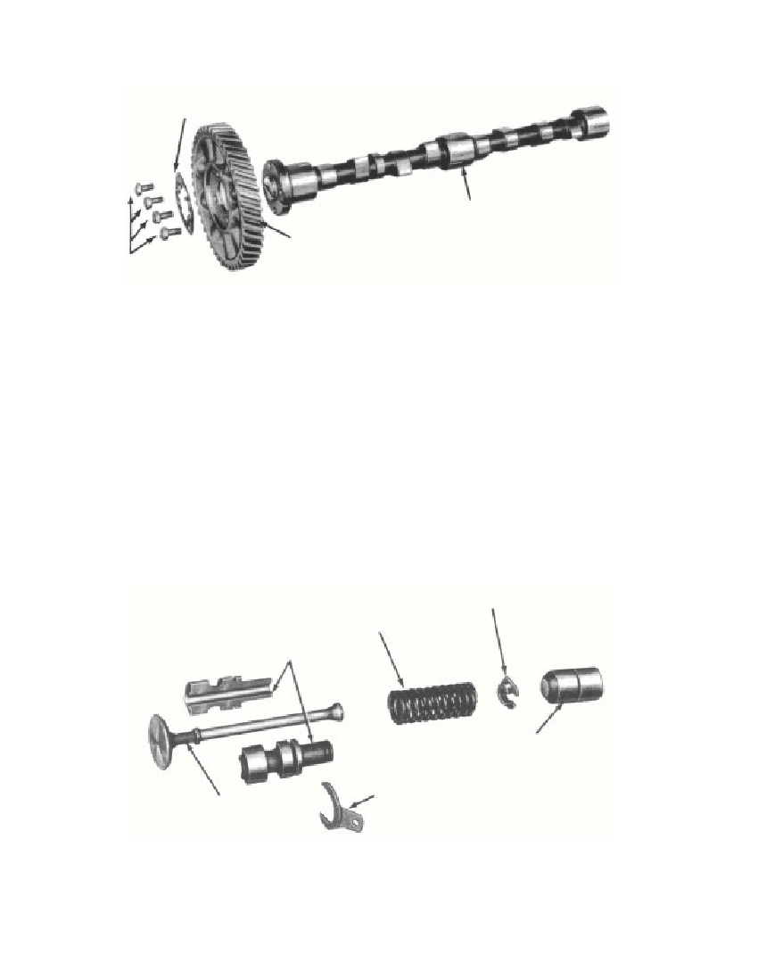 Fig. 25—Camshaft, Disassembledcams, or worn, corroded, scored, or discolored journals. Replace acamshaft if any of the journals measure less than 1.795 inches.Replace a camshaft gear that is visibly worn, broken, or has chippedteeth.To remove the camshaft gear, straighten the four tabs on thecamshaft gear locking ring. Remove the four cap screws and lockingring. Lift the camshaft gear from the camshaft (fig. 25). To install thecamshaft gear, place it on the camshaft, and install the locking ringand the four cap screws. Bend the tabs on the locking ring down ontothe cap screws.b. Valve Push Rods. Clean the push rods thoroughly. Replacepush rods if the diameter is worn to less than 0.998 inch, or if theyFig. 26—Valve Assembly, Disassembled3695-47§ 124. b.27CAMSHAFT—6250CAMSHAFT GEAR—6256RM-522LOCK WASHER-6258CAP SCREWS350400VALVE SPRING RETAINER—6514VALVE SPRING—6513VALVE GUIDE BUSHING—6510VALVE—6505VALVE GUIDE BUSHING RETAINER-6512PUSH ROD—6500RM-342
Free to read online. Contents · Where is the serial number on a 9N, 2N or 8N?