
Chapters
- Contents1
- Description and Specifications3
- Chapter 1 - Engine8
- Data8
- Accessory removal9
- Engine disassembly10
- Crankshaft and flywheel14
- Cylinder block16
- Pistons and connecting rods21
- Camshaft and valve mechanism26
- Cylinder head and front cover30
- Oil pump30
- Water pump32
- Governor34
- Oil pan, intake and exhaust manifolds38
- Assembly of engine40
- Installation of accessories46
- Definition of fits48
- Fits and tolerances50
- Torque wrench readings51
- Carburetor52
- Servicing the starter58
- Chapter 2 - Transmission61
- Chapter 3 - Power Take-Off71
- Chapter 4 - Belt Pulley75
- Chapter 5 - Rear Axle79
- Chapter 6 - Hydraulic System89
- Chapter 7 - Steering Gear101
- Chapter 8 - Service Bulletins111
- Bulletin Attachments126
Chapter 1 - Engine
Cylinder block page 18
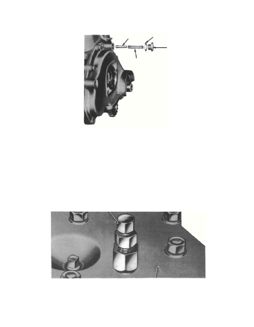 Fig. 12—Oil Relief Valve, Disassembledb. Steel Sleeve Replacement. Remove the sleeves from thecylinder block, using a crushing tool (fig. 14). Drive the tool all theway to the bottom of the cylinder, then pull the crushed sleeve outof the cylinder. Install new sleeves, using the replacer as shown infig. 15. After the sleeves are installed, use a piston (without rings)or a plug gauge in the cylinder to determine if the sleeve was properlyinstalled. If the piston or plug gauge has a tendency to stick, thesleeve was buckled during installation. Remove the damagedsleeve, install a new sleeve, and recheck it (fig. 15).Cylinder Head Stud Puller— 6067-ACYLINDER HEADFig. 13—Removing Cylinder Head Stud§ 122. b.RM-6393695-4718PLUNGER—6663SPRING—6654GASKET—6669OIL RELIEF VALVENUT—6666RM-511
Free to read online. Contents · Where is the serial number on a 9N, 2N or 8N?