
Chapters
- Contents1
- Description and Specifications3
- Chapter 1 - Engine8
- Data8
- Accessory removal9
- Engine disassembly10
- Crankshaft and flywheel14
- Cylinder block16
- Pistons and connecting rods21
- Camshaft and valve mechanism26
- Cylinder head and front cover30
- Oil pump30
- Water pump32
- Governor34
- Oil pan, intake and exhaust manifolds38
- Assembly of engine40
- Installation of accessories46
- Definition of fits48
- Fits and tolerances50
- Torque wrench readings51
- Carburetor52
- Servicing the starter58
- Chapter 2 - Transmission61
- Chapter 3 - Power Take-Off71
- Chapter 4 - Belt Pulley75
- Chapter 5 - Rear Axle79
- Chapter 6 - Hydraulic System89
- Chapter 7 - Steering Gear101
- Chapter 8 - Service Bulletins111
- Bulletin Attachments126
Chapter 1 - Engine
Cylinder block page 17
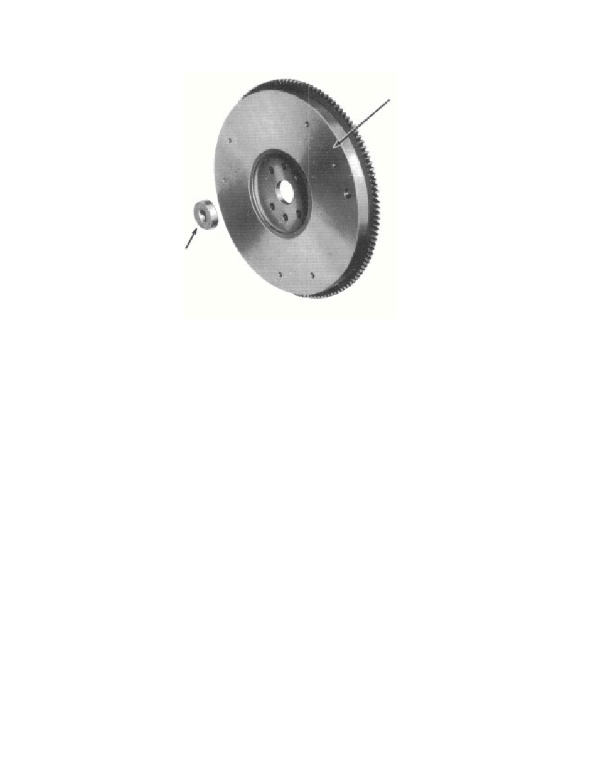 Fig. 11—Flywheel and Clutch Pilot Bearingblock might be cracked and should be checked thoroughly. Replacethe cylinder block if it is cracked. Replace any expansion plugs(fig. 1) that are loose.(1) STUDS. Replace damaged or broken studs (par. d below).(2) VALVE SEATS. Replace any valve seat insert that is crackedor that is loose in the cylinder block (par. f below). Reface valveseats where there is any indication that the valve has not beenseating, if new guides are to be installed, or if the width of the seat(fig. 16) measures more than 0.125 inch (par. e below).NOTE: If the engine has been completely disassembled, refaceall valve seats.(3) CYLINDER SLEEVES. Replace the cylinder sleeves (par.b. below) if a ridge is present at the top, or if the sleeves are col-lapsed or scored.(4) OIL RELIEF VALVE. Replace the oil relief valve spring(fig. 12) located in the cylinder front cover if its tension is less than44 ounces or more than 46 ounces when the length of the spring iscompressed to 1.40 inches. Install the valve, spring, and valve nut inthe cylinder front cover.3695-47§ 122. a. (4)17FLYWHEEL—6375CLUTCH PILOTBEARING—7600RM-589
Free to read online. Contents · Where is the serial number on a 9N, 2N or 8N?