
Chapters
- Contents1
- Description and Specifications3
- Chapter 1 - Engine8
- Data8
- Accessory removal9
- Engine disassembly10
- Crankshaft and flywheel14
- Cylinder block16
- Pistons and connecting rods21
- Camshaft and valve mechanism26
- Cylinder head and front cover30
- Oil pump30
- Water pump32
- Governor34
- Oil pan, intake and exhaust manifolds38
- Assembly of engine40
- Installation of accessories46
- Definition of fits48
- Fits and tolerances50
- Torque wrench readings51
- Carburetor52
- Servicing the starter58
- Chapter 2 - Transmission61
- Chapter 3 - Power Take-Off71
- Chapter 4 - Belt Pulley75
- Chapter 5 - Rear Axle79
- Chapter 6 - Hydraulic System89
- Chapter 7 - Steering Gear101
- Chapter 8 - Service Bulletins111
- Bulletin Attachments126
Chapter 1 - Engine
Assembly of engine page 45
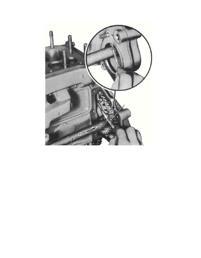 Fig. 54—Measuring Clearance Between Camshaft Gear and Cylinder Blocknut. If Marsden nuts (lock nuts) are used, tighten them from 40to 45 pounds-feet.g. Install Oil Pump Cover Assembly. Place the oil pump drivengear (fig. 31) on the shaft in the oil pump. Install the oil pump screencover assembly and gasket onto the oil pump. Secure the screencover assembly to the oil pump body with the three cap screws andlock wire.h. Install Cylinder Front Cover and Camshaft Gear SideCover. Hold the camshaft gear side cover and gasket in place onthe cylinder block, and install the two lock washers and cap screws.Install the oil slinger on the crankshaft.NOTE: Soak the crankshaft packing in oil for two hours beforeinstallation.3695-47§ 131. h.45Hammer HandleRM-584Thickness Gage
Free to read online. Contents · Where is the serial number on a 9N, 2N or 8N?