
Chapters
- Contents1
- Description and Specifications3
- Chapter 1 - Engine8
- Data8
- Accessory removal9
- Engine disassembly10
- Crankshaft and flywheel14
- Cylinder block16
- Pistons and connecting rods21
- Camshaft and valve mechanism26
- Cylinder head and front cover30
- Oil pump30
- Water pump32
- Governor34
- Oil pan, intake and exhaust manifolds38
- Assembly of engine40
- Installation of accessories46
- Definition of fits48
- Fits and tolerances50
- Torque wrench readings51
- Carburetor52
- Servicing the starter58
- Chapter 2 - Transmission61
- Chapter 3 - Power Take-Off71
- Chapter 4 - Belt Pulley75
- Chapter 5 - Rear Axle79
- Chapter 6 - Hydraulic System89
- Chapter 7 - Steering Gear101
- Chapter 8 - Service Bulletins111
- Bulletin Attachments126
Chapter 1 - Engine
Assembly of engine page 41
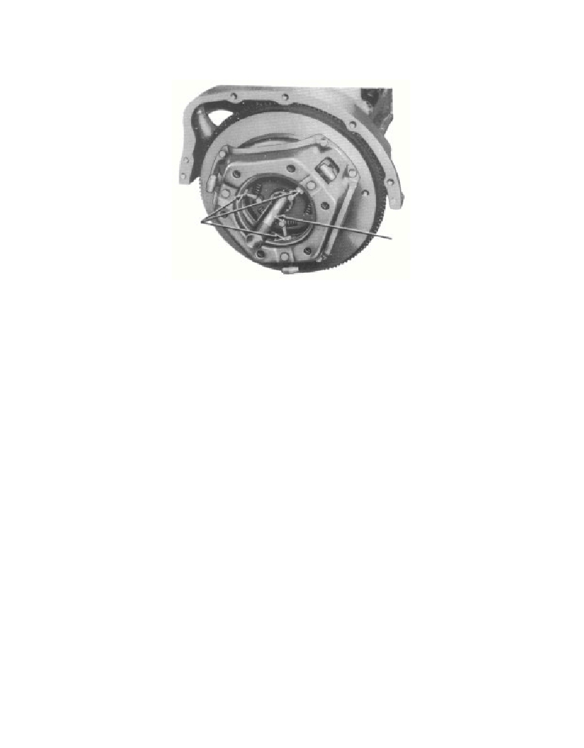 Fig. 47—Installing Clutch Disk and Pressure PlateIf the clearance exceeds 0.006 inch or is less than 0.002 inch, installa different center main bearing insert with a thicker flange to reducethe end play, or one with a thinner flange to increase the end play.Install lock wire in all of the main bearing caps.b. Install Flywheel. Place the flywheel in place on the crank-shaft. Make certain that there is no foreign matter or burrs betweenthe flywheel and crankshaft. Install the dowel retainer and capscrews. Tighten the cap screws from 65 to 70 pounds-feet. If selflocking cap screws are used, tighten from 75 to 80 pounds-feet.Check the flywheel runout with an indicator. If the flywheel has arunout of more than 0.005 inch, take the flywheel off and turn itone-half turn on the crankshaft, and install the dowel retainer andcap screws. If the runout is still more than 0.005 inch, replace orreface the flywheel. Install lock wire in the four cap screws.c. Install Clutch Disk and Pressure Plate. Block the threeclutch release levers down with wooden blocks (fig. 47). Positionthe clutch disk on the flywheel, and install a clutch pilot tool intothe pilot bearing and disk. Position the pressure plate on the fly-wheel. Install and tighten the six lock washers and cap screws.Remove the clutch pilot tool and the wooden blocks from thepressure plate.d. Install Camshaft Assembly. Install the camshaft in thecylinder block, being careful not to damage the camshaft bearing3695-47§131.d.41Wooden WedgesClutch PilotTool—7550-ARM-587
Free to read online. Contents · Where is the serial number on a 9N, 2N or 8N?