
Chapters
- Contents1
- Description and Specifications3
- Chapter 1 - Engine8
- Data8
- Accessory removal9
- Engine disassembly10
- Crankshaft and flywheel14
- Cylinder block16
- Pistons and connecting rods21
- Camshaft and valve mechanism26
- Cylinder head and front cover30
- Oil pump30
- Water pump32
- Governor34
- Oil pan, intake and exhaust manifolds38
- Assembly of engine40
- Installation of accessories46
- Definition of fits48
- Fits and tolerances50
- Torque wrench readings51
- Carburetor52
- Servicing the starter58
- Chapter 2 - Transmission61
- Chapter 3 - Power Take-Off71
- Chapter 4 - Belt Pulley75
- Chapter 5 - Rear Axle79
- Chapter 6 - Hydraulic System89
- Chapter 7 - Steering Gear101
- Chapter 8 - Service Bulletins111
- Bulletin Attachments126
Chapter 1 - Engine
Governor page 37
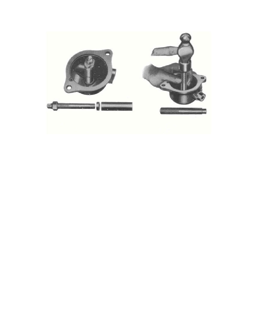 b. Repair. To replace the drive gear or ball bearing base, removethe drive gear from the shaft with a puller. Remove the ball bearingbase and lower race from the shaft as an assembly. Press the lowerrace out of the ball bearing base. To assemble the shaft, press thelower race assembly in the ball bearing base. Install the ball bearingbase assembly on the short end of the shaft (fig. 37). Press the gearon the shaft until the shaft is flush with the face of the gear.To replace the bushing, remove the elbow connection from thebody. Working through the elbow opening, drive the pin out of thefork and shaft with a small punch. Remove the levers from the body.Remove the bushing with an EZ-out type puller (fig. 40). To installthe bushing, place the thrust washer in the body (fig. 37), and drivethe bushing into the housing with a driver equipped with a pilot(fig. 41). Install the levers and fork in the body (fig. 36). Drive a newgrooved pin in the fork and shaft. Install the elbow connection inthe body.c. Assembly and Adjustments. To assemble the shaft as-sembly, place the four balls in position on the shaft, and install theupper race (fig. 37) over the balls. Install the thrust bearings andfork base on the shaft (fig. 37). Install the flat washer, shims, andhairpin clip (fig. 36) on the shaft.To adjust the shaft, clamp it and the driver assembly in thegovernor setting gauge as shown in fig. 42. The clearance betweenthe washer and fork base should be 0.220 inch to 0.230 inch. Add§ 128. c.3695-4737RM-634RM-633Fig. 41—Installing GovernorBushingFig. 40—Removing GovernorBushing
Free to read online. Contents · Where is the serial number on a 9N, 2N or 8N?