
Chapters
- Contents1
- Description and Specifications3
- Chapter 1 - Engine8
- Data8
- Accessory removal9
- Engine disassembly10
- Crankshaft and flywheel14
- Cylinder block16
- Pistons and connecting rods21
- Camshaft and valve mechanism26
- Cylinder head and front cover30
- Oil pump30
- Water pump32
- Governor34
- Oil pan, intake and exhaust manifolds38
- Assembly of engine40
- Installation of accessories46
- Definition of fits48
- Fits and tolerances50
- Torque wrench readings51
- Carburetor52
- Servicing the starter58
- Chapter 2 - Transmission61
- Chapter 3 - Power Take-Off71
- Chapter 4 - Belt Pulley75
- Chapter 5 - Rear Axle79
- Chapter 6 - Hydraulic System89
- Chapter 7 - Steering Gear101
- Chapter 8 - Service Bulletins111
- Bulletin Attachments126
Chapter 1 - Engine
Cylinder block page 20
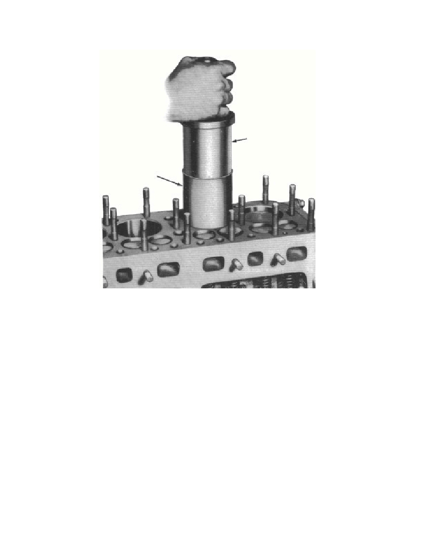 Fig. 15—Installing Cylinder Sleevee. Valve Seat Refacing. Reface each valve seat with a 90degree (included angle) valve seat grinding wheel or valve seatcutter until the face of the seat is "cleaned up" and free from pitsor nicks. If a valve seat cutter is used, it will be necessary to lap thevalves into the seat. The time ordinarily required to lap the valvesis saved by using an eccentric type valve seat grinder with whichthe grinding wheel contacts only one portion of the seat at anygiven time. If the grinder, including the pilot, is in good conditionand the grinding wheel is kept sharp and properly dressed, it ordin-arily is not necessary to lap the valves into the seats. After refacing,the width of the valve seat should not be more than 0.125 inch,measured across the face of the seat (fig. 16). If the seat is too wide,remove just enough stock from the top and/or bottom of the seatto reduce the width to 0.062 inch. Use a 120 degree (included angle)valve seat cutter for removing stock from the top of the seat and a60 degree (included angle) cutter for removing stock from thebottom of the seat.§ 122. e.3695-4720Sleeve ReplacerSLEEVERM-636
Free to read online. Contents · Where is the serial number on a 9N, 2N or 8N?