
Chapters
- Contents1
- Description and Specifications3
- Chapter 1 - Engine8
- Chapter 2 - Transmission61
- Chapter 3 - Power Take-Off71
- Chapter 4 - Belt Pulley75
- Chapter 5 - Rear Axle79
- Chapter 6 - Hydraulic System89
- Chapter 7 - Steering Gear101
- Chapter 8 - Service Bulletins111
- Bulletin Attachments126
- #1 Installing the new valve127
- #2 Adjustable tappet instructions129
- #3 Head bolt torque and tightening sequence130
- #4 8N engine ring overhaul, general specifications131
- #5 Servicing cast iron sleeves134
- #6 Oversize piston and ring sets135
- #7 Installing and timing the angle drive distributor137
- #8 Installing the 8N-10000-B generator140
- #9 Identifying and servicing carburetors142
Bulletin Attachments
#4 8N engine ring overhaul, general specifications page 132
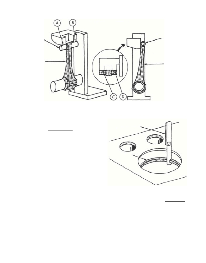 ATTACHMENT #4CHECKING CONNECTING ROD FOR BENDCHECKING CONNECTING ROD FOR TWISTROD ALIGNMENT AND PISTON PIN FITSCheck the connecting rod for alignment. Bentor twisted rods must be aligned within 0.0013 ateach end of the piston pin when the pin is centeredin the connecting rod. These measurements are takenon a standard connecting rod aligner at (A) and (B)for bend and at (C) and (D) for twist.The correct fit for a piston pin in the connec-ting rod bushing exists when the pin to be used willpass slowly through the bushing by its own weightwhen pin and bushing are dry. If bushing is exces-sively worn, drive it from the connecting rod witha suitable driver. Press a new bushing into therod. Drill the two oil holes in the bushing to thesame size as the holes in the rod. Ream and burnishor hone the bushing to 0.7505 inch diameter.Piston pin to piston fit is 0.000-0.0002. Thismay seem tight, but under operating temperature theexpansion of the piston will permit sufficientclearance for efficient operation.PISTON RING END GAPPlace each new piston ring in the cylinder, andpress it about halfway into the cylinder bore withAN INVERTED PISTONso the ring will be squarewith the cylinder wall. Measure the ring gap witha thickness gauge. If the gap is less than 0.007-0.017 in the top compression ring and less than010-.017 in the second compression and oil ring,remove the ring and file it with a fine cut fileuntil the correct ring gap is obtained. Ring endgap should be staggered on the piston at 120° whenengine is being assembled.MEASURING PISTON RING END GAPPage 2 of 3132TORQUE WRENCH READINGSTorque ValuesMain Bearing Nuts75 - 85 Lbs. Ft.Main Bearing Place Bolts90 -100 Lbs. Ft.Connecting Rod Nuts-Castellated 35 - 40 Lbs. Ft.Connecting Rod Nuts-Self Locking 35 - 40 Lbs. Ft.Connecting Rod Nuts-Marsden 35 - 40 Lbs. Ft.Connecting Rod Lock Nuts-Pal4-5 Lbs. Ft.Cylinder Head Nuts50-55 Lbs. Ft.Cylinder Head Cap Screws65 - 70 Lbs. Ft.Fly Wheel Self Locking Cap Screws 75 - 85 Lbs. Ft.Spark Plugs25 - 30 Lbs. Ft.Oil Pan to Cylinder Block15 - 18 Lbs. Ft.PISTON RINGFEELER GAUGEPISTON PINCONNECTING RODCONNECTING ROD ALIGNERTOP VIEWPISTON PINCONNECTING ROD
Free to read online. Contents · Where is the serial number on a 9N, 2N or 8N?