
Chapters
- Contents1
- Description and Specifications3
- Chapter 1 - Engine8
- Chapter 2 - Transmission61
- Chapter 3 - Power Take-Off71
- Chapter 4 - Belt Pulley75
- Chapter 5 - Rear Axle79
- Chapter 6 - Hydraulic System89
- Chapter 7 - Steering Gear101
- Chapter 8 - Service Bulletins111
- Bulletin Attachments126
- #1 Installing the new valve127
- #2 Adjustable tappet instructions129
- #3 Head bolt torque and tightening sequence130
- #4 8N engine ring overhaul, general specifications131
- #5 Servicing cast iron sleeves134
- #6 Oversize piston and ring sets135
- #7 Installing and timing the angle drive distributor137
- #8 Installing the 8N-10000-B generator140
- #9 Identifying and servicing carburetors142
Bulletin Attachments
#1 Installing the new valve page 127
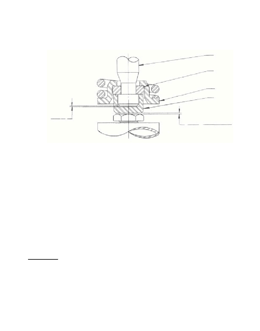 ATTACHMENT #1 - Page 1INSTALLATION INSTRUCTIONS FOR NEW VALVE IN THE FORD TRACTOR ENGINEA new type exhaust valve assembly is illustrated and describedabove. The assembly consists of a valve "A", two keys "B", a cap "C", anda special spring retainer "D"; the standard spring being used with thisassembly.The parts, when correctly assembled, permit the valve to be en-tirely free of the spring force during the lift portion of the cycle. Atthe beginning of lift, the tappet lifts the keys through the medium of thecap which, in turn, lifts the spring retainer and spring, thus leaving thevalve free of the influence of the spring with respect to cocking and un-due side-loading. During the normal travel, the valve can turn, oscillate,or otherwise move in its guide. With this action, the deposits that tendto build up at the head end of the guide and on the stem are constantlyscrubbed, thus preventing sufficient build-up to take up the normal clear-ance. Furthermore, the deposits that occur between the valve face and itsmating seat cannot build up excessively or unevenly; the net result beingthat a much better contact is maintained between the two faces, which in-sures proper sealing.INSTALLATIONThe successful operation of the new valve assembly depends, to alarge extent, on proper installation. The clearance required is con-trolled by the length between the face of the undercut in the valve and tipend, and the depth of the cap. If the cap depth is too shallow, it willnot lift the keys and springs and, on the other hand, if the cap is toodeep or the length between the groove face and tip is too great, the clear-ance will be excessive, resulting in a high wear rate and possible valvebreakage.127ABDC.0/4 CLEARANCE.0/6.0002.004
Free to read online. Contents · Where is the serial number on a 9N, 2N or 8N?