
Chapters
Chapter 7 - Steering Gear
Assembly page 106
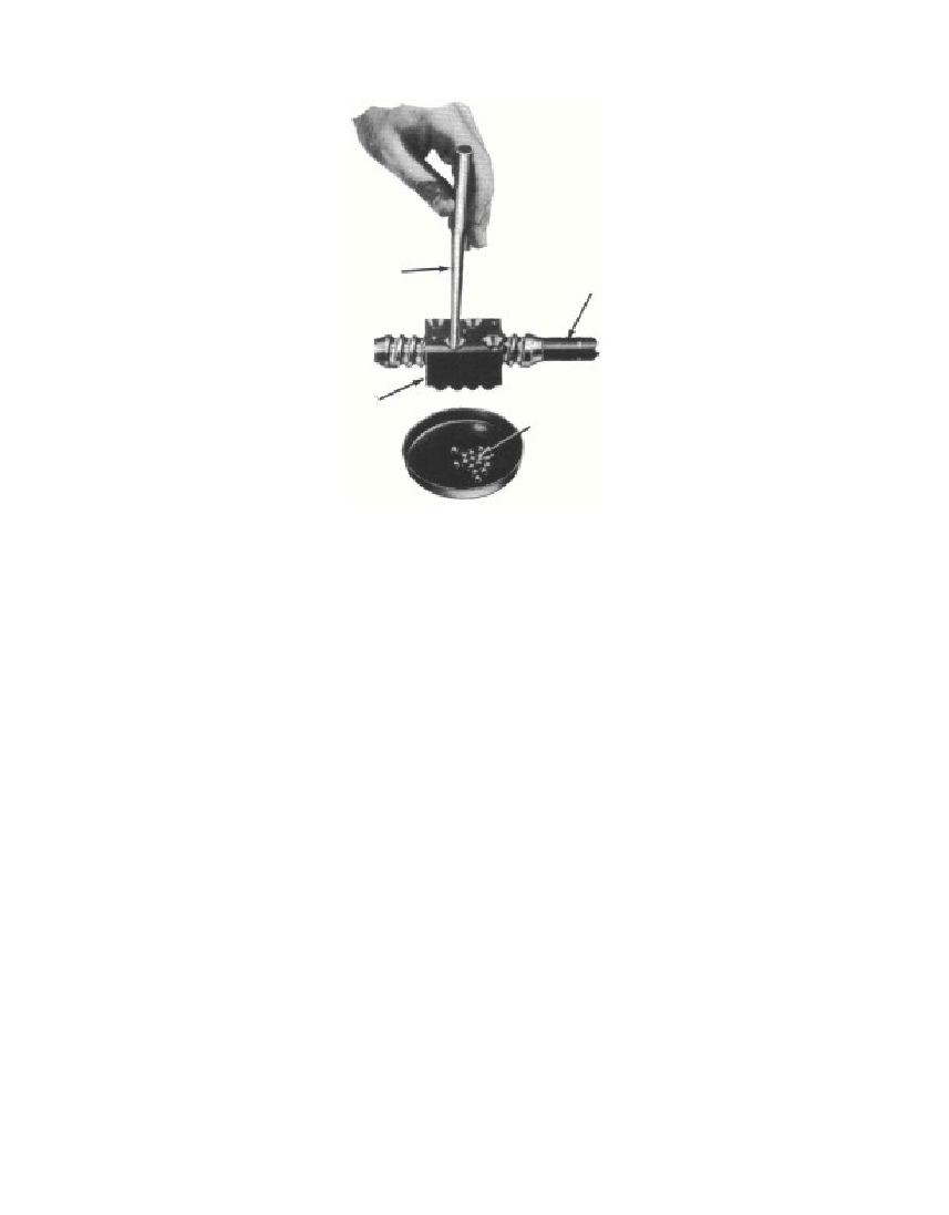 Fig. 4—Aligning Ball Nut on Steering Tube Shaftit is1/8inch below the face of the hub. Press the new outer bushinginto the housing until it is level with, or slightly below, the bottomof the counterbore. Line ream both bushings in place to 1.125-1.126inches in diameter.124. ASSEMBLY.Assembly should be accomplished only when inspection showsthat every part is in a serviceable condition.a. Steering Tube Shaft and Ball Nut. Place the steering shafton a bench and position the nut over the middle section of the wormwith the ball retainer holes on top. Align the ball retainer holes withthe grooves in the worm on the steering shaft (fig. 4). Drop 20 ballsinto one of the retainer holes, then slowly rotate the steering shaftto carry the balls away from the hole. Continue dropping the ballsinto the hole until the ball circuit is full to the bottom of both holesor until the end of the steering shaft worm has been reached. Wherethe balls were stopped by the end of the worm, they should be heldin position with a clean, blunt tool while the steering shaft is rotatedin the opposite direction. This will make it possible to drop more ballsinto the retainer hole. Extreme care should be exercised to makecertain that no balls are outside the regular ball circuits. If balls§ 124. a.3730-47J106STEERING SHAFTPunchBALL NUTBALLSRM-667
Free to read online. Contents · Where is the serial number on a 9N, 2N or 8N?