
Chapters
Chapter 7 - Steering Gear
Assembly page 107
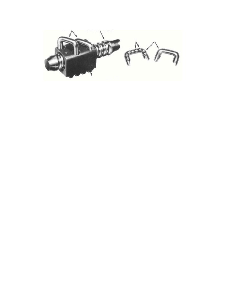 Fig. 5—Removing or InstallingBall RetainerFig. 6—Filling BallReturn Guideremain in the groove between the two circuits, or at the ends, theseballs cannot circulate and will cause ultimate failure of the steeringgear.It may be necessary to rotate the steering tube shaft alternatelyin both directions while, at the same time, holding the balls in place.This will make it possible to completely fill the ball circuit.Lay one-half of the retainer on the bench, and fill it with 10 ballsfor the circuit being filled. Position the other half of the retainerover the balls, plug the ends with heavy grease, and insert theretainers into the retainer holes in the nut (fig. 6).The second ball circuit is filled in the same manner.Install the retainer clamp and three screws.b. Installing and Adjusting Steering Tube Shaft and Sectors.Position a roller bearing in the bearing race in the housing on theupper bearing race of the shaft (fig. 2).Place shims on the housing to an approximate thickness of 0.050inch. Hold the steering tube shaft and ball nut assembly in place inthe housing, with the rack teeth toward the sectors and the ballnut in the approximate center of the worm. Install the steering tube.Do not tighten the bolts so tight that damage to the bearings willresult, especially when an insufficient thickness of shims have beenused. Install the steering wheel and measure the force required torotate it. This should be from 1 to 11/2pounds on a spring scale(fig. 7). Add or remove shims as required until the correct force isobtained. Be sure that the pulling force of the scale is at right anglesto a steering wheel spoke when taking measurements.3730-47J§ 124. b.107RETAINERS STEERING SHAFTBALLS RETAINERSRM-666RM-665BALL NUT
Free to read online. Contents · Where is the serial number on a 9N, 2N or 8N?