
Chapters
Chapter 6 - Hydraulic System
Hydraulic system adjustments page 99
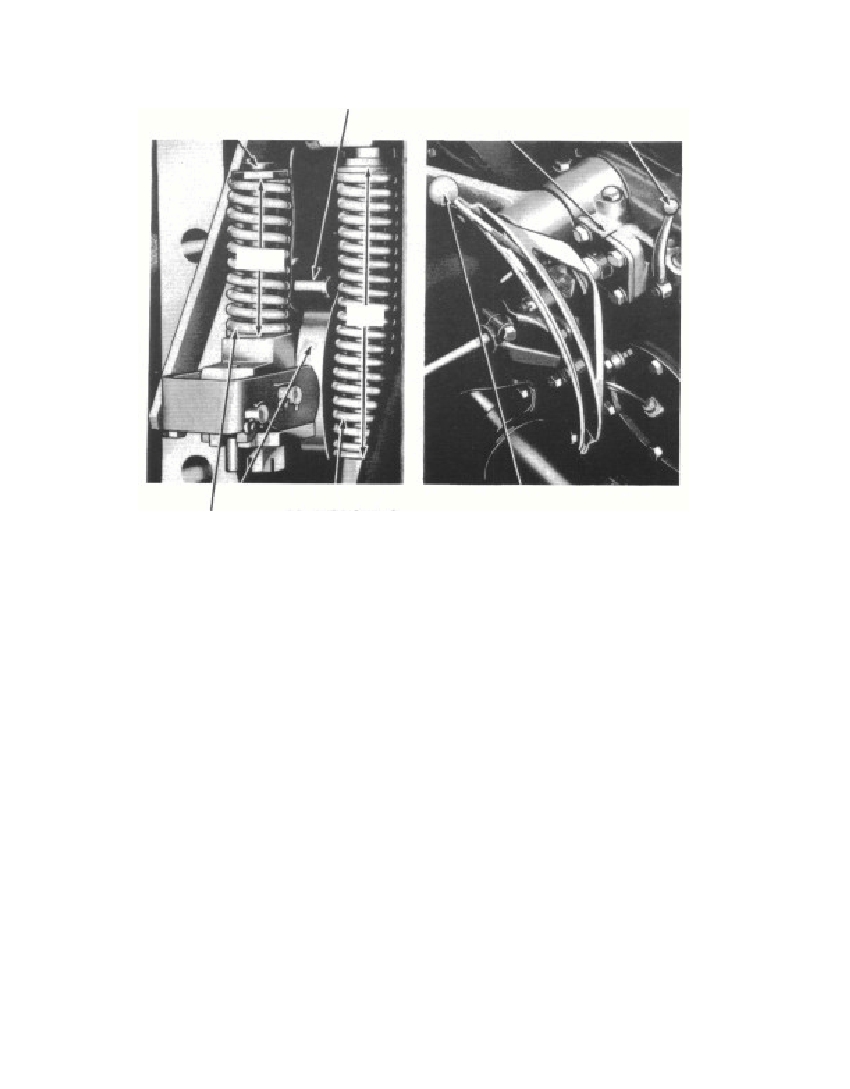 (2) Examine the constant draft spring adjustment nut (fig. 29).If it is a lock nut, it should be tightened until the washer bearsagainst the shoulder. If it is a standard castellated nut with a cotterpin, the nut should be adjusted to give the correct length of theconstant draft spring, then the cotter pin can be installed. Theconstant draft spring should be 3.58 inches long (slightly over 39/16inches is satisfactory) as shown in fig. 30.(3) Examine the top of the quadrant supports plate for locatingmarks as shown in fig. 31. The quadrant support cap screws shouldbe loosened, locating marks aligned, and the cap screws tightened.If there are no locating marks, remove two cap screws from thequadrant support plate, loosen the two remaining cap screws, andcenter the slot in the quadrant support plate on the cap screws asaccurately as possible. Replace and tighten the cap screws thatsupport the quadrant.(4) Place the position control lever in the position shown in fig.29. Move the hydraulic touch control lever until there is an opening3730-47J§ 143. b. (4)99Fig. 30—Constant Draft Control andFig. 31—Quadrant LockingPiston Control SpringsMarkPOSITION CONTROL PINLOCATING MARKS POSITION LEVERPOSITION CONTROLSPRING ADJUSTMENT BOLT129/32"3.58CAM CONSTANT DRAFTCONTROL SPRINGHYDRAULIC TOUCH CONTROL LEVEROM-418POSITION CONTROL SPRING OM-417
Free to read online. Contents · Where is the serial number on a 9N, 2N or 8N?