
Chapters
Chapter 6 - Hydraulic System
Hydraulic pump page 93
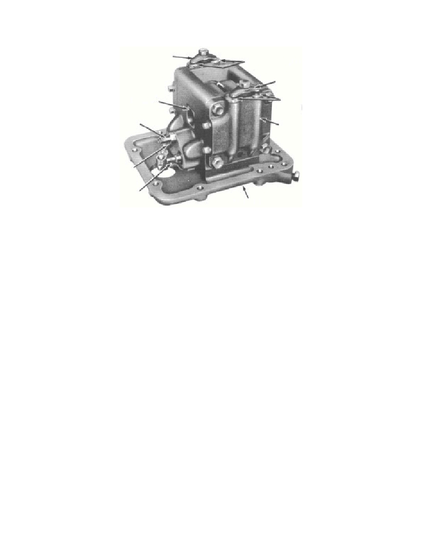 woodruff key on the hydraulic touch control lever shaft. Install thehydraulic touch control lever on the shaft making sure that it slidesfreely on the woodruff key, and secure it in place with a flat washer,spring, and nut. If the woodruff key fits too tightly in the touch con-trol lever and therefore cannot slide freely, the spring which main-tains a constant pressure on the friction disk will be ineffective.Install the hydraulic touch control lever retainer. Connect the posi-tion control lever to the position control linkage.(3) ASSEMBLE RAM CYLINDER AND PISTON. Assemblethe rings onto the ram cylinder piston and equally space the ringgaps around the piston. Install the piston in the ram cylinder. Usingnew gaskets (three required) bolt the ram cylinder to the hydraulicunit cover. Install the piston rod.142. HYDRAULIC PUMP.The disassembled hydraulic pump is shown in fig. 22.a. Disassembly. Remove the safety valve and check valve.Remove the cotter pin which secures the valve control lever to thebase. Remove the cotter pin and clevis pin which secure the exhaustvalve to the control lever. Remove the control lever. Remove thefour cap screws which secure each valve chamber cover (fig.-22) tothe base. With a soft hammer, tap the valve chambers off the base.Lift the cam and piston assembly out of the base. Remove the powertake-off shaft bushing (figs. 22 and 26) from the base. Remove the3 730-47J§ 142. a.93CLAMPVALVE CHAMBER PLUGSCLAMPVALVE CHAMBERPLUGSVALVE CHAMBERPOWER TAKE-OFFSHAFT BUSHINGSAFETY VALVEOUTLET VALVEINLET VALVEFig. 22—Hydraulic PumpPUMP BASERM-599
Free to read online. Contents · Where is the serial number on a 9N, 2N or 8N?