
Chapters
Chapter 6 - Hydraulic System
Hydraulic unit page 92
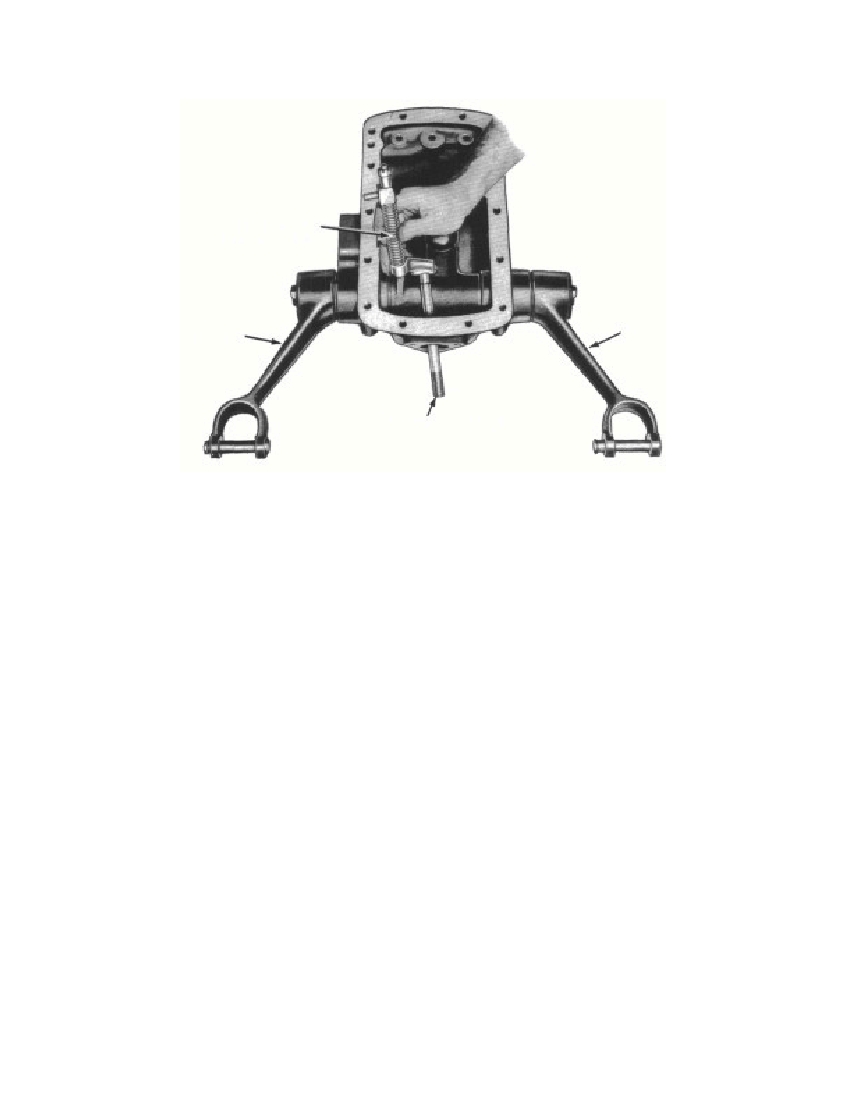 Fig. 21—Install Constant Draft Control Linkagec. Assembly. The hydraulic unit may be assembled by sub-assemblies. The sequence of assembling subassemblies onto thehydraulic unit cover may be changed from that given below.(1) ASSEMBLE LIFT ARMS AND SHAFT. Hold the ram armin place in the hydraulic unit cover, and install the shaft. Install thetwo bushings (fig. 20) on the shaft. Install the two lift arms on theshaft, and secure each arm to the shaft with a flat washer, lockwasher, and two cap screws. The lift arms should be tightened enoughto prevent end play of the shaft. The lift arms should not bind to theextent that they will not settle under their own weight.(2) ASSEMBLE CONTROL LINKAGE. Install the draft con-trol linkage as shown in fig. 21. Place the position control linkage onthe hydraulic touch control lever shaft, and insert this assembly inthe hydraulic unit cover. Install the control arm on the draft controllinkage and the hydraulic touch control lever shaft. Secure the con-trol arm in place with a castellated nut and cotter pin.Position the three-cornered plate with the pin at the top on thehydraulic unit cover and secure with three cap screws. Install a newfelt washer in the control spring seat. Install the control spring seat,control spring, and yoke (fig. 18). Mount the quadrant, using a newgasket, on the hydraulic unit cover. Install a new friction disk and§ 141. C. (2)3730-47J92LIFT ARMRM-624CONTROL SPRING PLUNGERCONSTANT DRAFTCONTROL SPRINGLIFT ARM
Free to read online. Contents · Where is the serial number on a 9N, 2N or 8N?