
Chapters
Chapter 6 - Hydraulic System
Hydraulic unit page 90
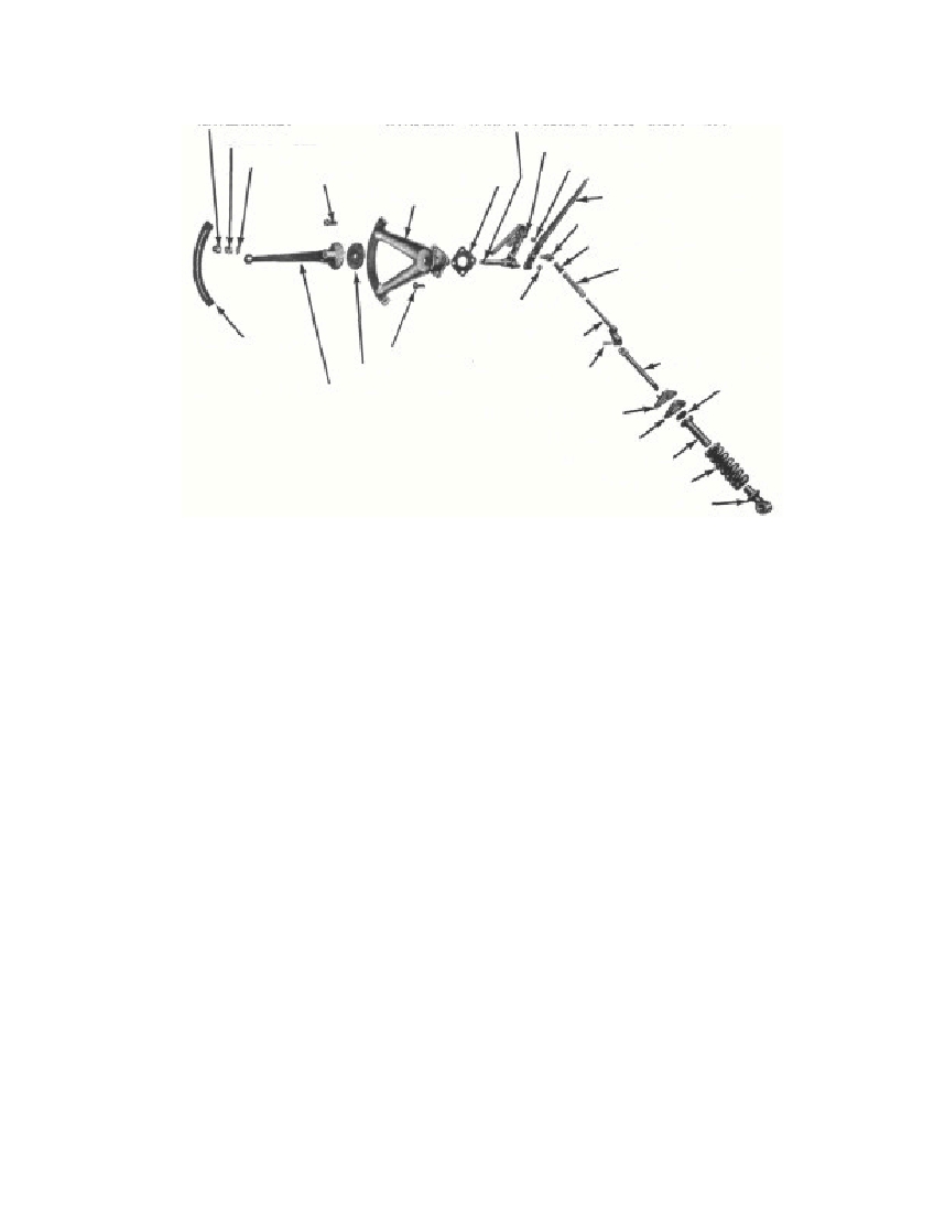 (2) REMOVE CONTROL LINKAGE. Remove the hydraulictouch control lever retainer (fig. 18) from the quadrant. Remove thenut, spring and flat washer that secure the hydraulic touch controllever shaft. Remove the hydraulic touch control lever, woodruff key,and the friction disk from the shaft.Remove the cotter pin that attaches the linkage which secures theposition control lever to the position control linkage (figs. 17 and 18).Remove the control arm, draft control linkage, and position con-trol linkage.(3) REMOVE LIFT ARMS AND SHAFT. Remove the twocap screws, lock washer, and the flat washer from each arm. Removethe lift arms from the shaft. Remove the shaft from the hydraulicunit cover. Remove the ram arm and the remaining bushing from thehydraulic unit cover (fig. 19).b. Inspection and Repair. Clean all parts thoroughly in cleaningfluid. Scrape off any incrustated deposits on the cover or parts. It isvery important that any foreign matter that might get into the oilbe removed.(1) COVER. Replace the cover if it is cracked or damaged in anyway.§ 141. b. (1)3730-47J90Fig. 18—Hydraulic Control LinkageHYDRAULIC TOUCH CONTROL LEVER SHAFT—517POSITION CONTROL LINKAGENUT-33965-SCONTROL ARM—504SWIVEL—692BUSHING-691CONSTANT DRAFTSPRING—539NUT-351047SPRING—522WASHER-34748BOLT—20302-S7QUADRANT—515GASKET-532RETAINER—520HYDRAULIC TOUCH CONTROL LEVER—512FRICTION DISC—518BOLT-21443-S7NUT—33965-SCONNECTING LINK-540PIN—73956SUPPORT PLATE—624COVER PLATE—527SPRING SEAT-525SPRING—547YOKE—546-CRM-626PLUNGER—541FELT-529
Free to read online. Contents · Where is the serial number on a 9N, 2N or 8N?